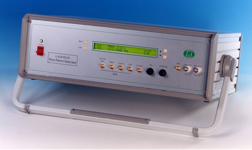
LA 19-02-01 12 Gb/s 射频信号源 PULSEPATTERN GENERATOR
产品型号:LA19-02-01 12 原产地:英国
所属类别:信号发生器
产品简介:
The LA19-02-01 is a pseudo random pulse pattern generator capable of operation up to 12 Gb/s.

LA 19-02-01 12 Gb/s 射频信号源 PULSEPATTERN GENERATOR
产品型号:LA19-02-01 12 原产地:英国
所属类别:信号发生器
产品简介:
The LA19-02-01 is a pseudo random pulse pattern generator capable of operation up to 12 Gb/s.
The LA19-02-01 is a pseudo random pulse pattern generator capable of operation up to 12 Gb/s. The unit can accommodate two internal clock generators and it accepts an external clock input. It provides a fast pulse output up to 4 Vppsuitable for applications such as testing high bit rate communication components, fast pulse amplifiers and high speed logic circuit development.  ●Operation to 12 Gb/s ●35 psrise and fall times ●Choice of pattern lengths ●User-programmable 128 bit pattern ●4 Vppadjustable output amplitude ●Low noise internal clocks ●Remote control through serial interface ●Low cost |
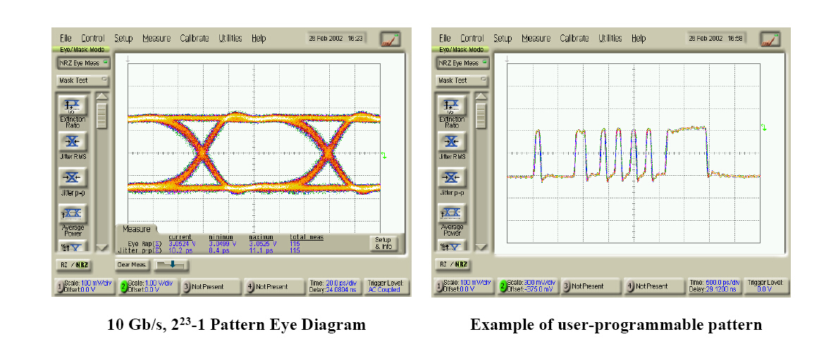
The LA19-02-01 provides a binary sequence signal synchronised to either an internal or external clock. The sequences available are pseudo random (223-1 and 27), clock/2, clock/4, burst and a user-programmed 128 bit sequence. The 223-1 PRBS sequence is in accordance with the CCITT recommendation and the sequence is non-inverted. The 27PRBS sequence is a zero substitution pattern where the longest run of zeros has been extended to eight zeros and the following bit set to one, thereby making the sequence 128 bits long.The main output is ac-coupled and provides a user adjustable 2 to 4 Vppsignal with fast transitions of 35 ps. An internal bias-T is provided to allow a dc offset to be superimposed on the main data output. The bias-T supports a dc current of up to 100 mA. The waveform crossover can be adjusted over a range of +5% from the front panel. The auxiliary data output is a dc coupled, logic level output (0 to -0.8 V typical) with the same signal polarity as the main output.Three types of synchronisation output signals are available, Clock, Clock/16, and Pattern. The clock is a sine wave with a typical amplitude of 0.8 Vpp. The clock/16 is derived from the clock signal by means of low noise dividers. The typical amplitude of this is 0.8 Vpp. The pattern synchronisation output produces an output synchronised to the length of the sequence selected. Thisallows, for example, the individual data bits to be observed on a sampling oscilloscope. It is available on all settings except the 223-1 pattern length setting.A bias-T is included on the clock output. This allows a dc offset to beadded to the ac clock signal. The maximum dc current allowed is 100 mA. Also, the clock output includes a mechanically adjustable phase shifter able to provide at least 540Oof phase shift at 12 GHz.10 Gb/s, 223-1 Pattern Eye DiagramExample of user-programmable patternPRBS223-1Clock 1Clock 2128 bitprogwordMUXClockdistributionExt ClockMain data outputAux data outputdc biasClock outputdc biasphase adjustPattern syncCk/16 outDW96404_4 Apr 10Simplified Block DiagramChancerygateBusiness Centre, Unit 5Red Lion Road, Surrey KT6 7RA, UKhttp://www.latechniques.comProgrammable PatternA 128 bit user-defined pattern can be programmed into the LA19-02-01 via the front panel. This is stored and retained indefinitely in internal memory until re-programmed. The auxiliary data output is dc-coupled and this will maintain waveform fidelity even when the programmed patternentered is unbalanced.Remote ControlAn RS232 serial interface allows remote control of the instrument. This allows most front panel settings to be remotely adjusted. The exceptions are the clock phase shift and the main output crossover settings. The serial interface supports a single baud rate of 1200 bits per second.Available OptionsOption 1removes the 4V output voltage capability and associated bias-T and substitutes it with a dc coupled, logic level (0.8 V, typical) low jitter output (Q). The auxiliary output then becomes an inverted data output (Q bar).Option 2provides the same logic level outputs as option 1 but with the Q output being ac coupled together with an internal bias-T to provide a dc offset.ORDERING INFORMATIONLA19-02-01 Pattern generatorClock1 xx GHz(xx is frequency in the range 2 to 12 GHz)OptionsClock2 xx GHz(xx is frequency in the range 2 to 12 GHz)Option 1: Removes 4 V ac coupled, adjustable output and substituted witha dc coupled, fixed level, low jitter output. This option provides dc coupled Q and QbaroutputsOption 2: As option 1 but with the Q output ac coupled and including a bias-T to allow a dc offset to be superimposed on the data. |
日本岩通计测IWATSU - 德国PMK - 牛顿N4L- GWINSTEK- 日本APOLLOWAVE - 德国 DR HUBERT 中国总代理
BH分析仪|半导体曲线图示仪|探针台-探针卡|碳化硅双脉冲示波器|光隔离探头|特高压浮地|PSM3750频率响应|罗氏电流线圈|PMK高压差分探头|压电超声高频功放
 技术咨询
技术咨询 留言反馈
留言反馈


